Posts

Clarifying the notion of burden factor (drag factor) – Part three

Final Comments

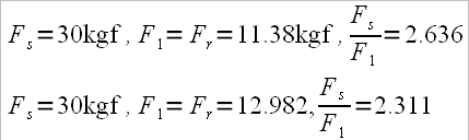
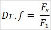
After the previous conclusions we can say that the drag factor, at any moment while passing through the water, is actually the ratio of the pushing force against the stretcher (Fs) and the boat propulsion force (F1). We will note the drag factor with Dr.f, thus obtaining the formula:

The burden factor will be different at catch compared to the perpendicular on the boat or compared to finish.
The lowest value of the drag factor will be in the oar’s perpendicular position onto the boat’s longitudinal axis, where we have maximum efficiency.

Dr. Valery Kleshnev, PhD in biomechanics, says: “The span/spread doesn’t affect the gearing. Decreasing the span/spread with 2cm (in a sculling boat, decreasing on one side is actually 1cm) will increase the catch angle by 0.5 degrees.”
The same increase of catch angle can be achieved through other methods: moving the stretcher or shortening the internal lever.
Now we are able to increase or decrease the total length of the oar by 10 -12 cm (not possible 20 years ago), this means that we can simplify how we find the drag factor (Dr.f), using fewer variables without the need to change at the same time the span/spread and the internal lever (ie total length of the oar).

The sequence of operation is:

1. Determination of the drag factor depending on the result on the ergometer – 2000 m
For example: for a result of 6 minutes – 2000 m, Dr.f will be 2.74 for “M2-” and 2.26 for “M1x” (calculated after the Australian model) and for a result of 7 min – 2000 m the Dr.f is 2.70 for “W2-” and 2.25 for “W1x”.

2. Measurement of the specific amplitude (leg length plus mobility) and taking into account the rower’s individual parameters: trunk height, shoulder breadth, fist width and the angle of the blade in finish position we will determine:
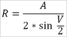
– rowing sector (total angle “V” from the catch to the end of the stroke) after the formula:A max : v max

– projection of the internal lever (R),
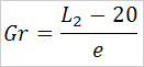
– span/spread (e)

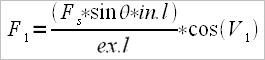
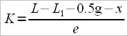
Since the calculation of the drag factor proposed by me has the formula:

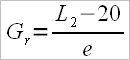
it involves the measuring device for the stretcher force, and a special measuring angle device used to measure the angle between the oar’s handle and the rower’s arm, which is possible only in national teams, we can either relate to the Australian method of calculation where we already have available the tables (rigging manual), especially since us, Romanians, use Crocker type oars. According to the formula:

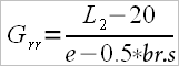
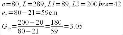
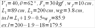
either to the calculation model of “gearing” proposed by mr. V. Kleshnev, namely the external lever (ex.l) divided by the effective internal lever (in.l)

ex.l =L2 – 2 – 18 and in.l = L1 + 2 – 0,5 f (scull oars)
ex.l = L2 – 2 – 24 and in.l = L1 + 2 – 2f (sweep oars where “0.5f” means half of the fist’s width and “2f” means twice the fist’s width)

In the first case, even if the Australian method is valid only for the orthogonal position of the oar, let’s remember that individualization has been already achieved by establishing the total angle (V), the projection of the internal lever (R) and the span/spread (e) depending by the specific amplitude (A) of each rower.

Should be noted that the real boat specific amplitude (length of stroke) is 6% lower than the measured specific amplitude (Lp + mobility) for sculling boats.

I chose to measure these two parameters (leg length and mobility) because one cannot cheat any more like in the case of directly measuring in the boat, where because of the desire to have a bigger amplitude, rower stretch excessively at attack or lean too much at finish.

In the second case, I would like to make a note of a similar model that I’ve encountered in “Topoergonomia in canotaj” (C. Radut, J. Billard) called the apparent lever ratio, but in that case the author only talked about the handle’s length (L1) and the external length of the oar, from the collar to the external end of the blade (L2).

The equivalent for 6 min. – 2000 m ergometer is “M2-” = 2.350 and “M1x” = 2.100, for 7 min. – 2000 m ergometer “W2-” = 2.300 and “W1x” 2.090.

For other boats there are also calculated tables.

When calculating the drag factor according to either the Carl Adam model, the English or the Australian model they do not include in the calculation the internal lever, but only the external lever, complete or incomplete, divided by the span / spread.
When calculating the drag factor according to Kleshnev’s formula he does not enter the calculation span / spread, but only the effective external lever (ext.l) divided by the effective internal lever (int. l).
Is to decide which one to choose, which one is better.

Continuation the notion of drag factor (burden factor) – Part Two

The propulsion force of the boat was already explained in the previous article but there I was referring only to sweep boats.

For scull boats the situation is somewhat different. If in the case of the sweep boats, the vector of the force applied at the handle overlapped the longitudinal axis of the boat, respectively half of the distance between the rower’s two shoulders, in the case of the scull boats this vector is placed on a line parallel to the longitudinal axis of the boat at a distance equal to half of the distance between the two shoulders.

The questions is: Why isn’t it confused with the longitudinal axis of the boat since the stretcher pushing force is exercised along to it?

The answer: Applied force is transmitted through the legs, trunk and arms. It is known that the leg’s strength is higher than the strength of the arms. The stroke’s charge will be felt in the shoulder joint, which means that we can push with the feet as much as the shoulder’s joint will allow us to (muscles, tendons, ligaments, joint capsule). As a reference we’ll take this line, parallel to the longitudinal axis, but because the action takes place symmetrically on both sides, the two vectors parallels to the shoulders lines can be considered componenets of the vector which pushes into the palonier along the longitudinal axis. This means that the span (spread) is actually smaller with half the width of the shoulders (shoulders breadth – Br.s).

Real spread (er) = Normal spread (e)- 0.5 * shoulders breadth (Br.s)
er = e – 0.5*Br.s

If we want to calculate after the Autralian model where

the formula becomes

Example:

If we want to calculate the drag factor (burden factor) in it’s different momments, we’ll use the same formula as in the previous article:

where now

(handle minus half the fist’s width, and theta is the angle between the handle and the longitudnial axis of the arm)

Note: in the formula there s “cos(V1)”, which means that the momment of the stroke for which we calculate it’s before the orthogonal pozition of the oar (toward the attack). If the momment for which we calculate is beyond the orthogonal position, meaning more towards the end of the stroke, then we’ll take into account cos(V2). For the orthogonal position, either of the two “cos(V1)” or “cos(V2)” aren’t necessary, because F1=Fr.

Regarding the stretcher pushing force, because the calculation is made for only a single oar, we’ll take into consideration 0.5Fs.

Example:

According to the formula:

But, because we have calculated the draging (burdening) factor only to one oar (on one side), we’ll duble the result and get F1(total)=9.688Kgf

If we do a comparison to the calculation of a sweep boat as we did in the previous article we will notice that the ration between the stretcher pushing force (Fs)(Fs=30Kgf) and the orthogonal position propelling force (F1=Fr) will return some results that can be considered as “burdening coefficient” (drag factor)

Clarifying the notion of drag factor (burden factor) – Part One

Along the years in specialty literature there are noticed three approach methods of the drag factor (burden factor) in regards to rowing:
1 – Carl Adams and the German School for rowing defined the “drag factor” and noted it with K. The formula was:

where:
L – total length of oar
L1 – inboard length of oar
0.5g – half of the gate’s width
x – distance between end of oar to a point “x”, the so called pressure point.
And spread (“e”) is considered the distance from the longitudinal ax of the boat to the pin.

Considering the above formula we realize that in the calculus of K there are included: L, x (a part of L2 , because L-L1=L2 from which we subscribe half of gate’s width and the distance from the tip of the oar to the point x).
Depending of the blade’s length and width there is a formula to calculate x.

where:
0.45 is a constant
Lb – length of blade
700 – another constant
wb – width of blade

which results that.

The formula was given for the sweep blade type Macon, but it’s also valid for Big Blade.

2 – Supporters of the English Rowing School talk about “gearing”, let’s note it with Ge, and the formula of calculus is:

3 – Researchers from the Australian Institute of Sport propose another approach, which they name “gearing ratio”, which we’ll note as Gr, and the formula for this is:

where:
L2 – outboard length of oar
and 26 is a constant.

This formula is valid for the big blade oar made by the builder Crocker with Lb=55cm(blade length) and wb=25cm (blade width).

1.1 Carl Adams’s formula although it’s the most scientific elaborated, because it can be applied to oars of different measurements, I don’t consider it to be so realistic, because the point x is too close to the oar’s shaft.
“x” could rather be a rotation point of the blade during the drive, for instance:

From this formula we notice that x is just 2.25 cm away from the oar’s shaft. Yet finding the value of x will be useful to determinate the travel distance of the boat during the drive if we know “V” (angle covered by the oar’s handle from catch to finish).

2.1 Approach of the drag factor (burden factor) after gearing:

Again, I consider this formula inconclusive because the oar’s dimensions aren’t included (blade’s width and length).

3.1 Even though it refers only to the Crocker blade, I think the Australian approach is the best yet. I propose the following formula to be used with other kinds of blades (Concept II or Empacher, which have different dimensions) :

where:

and the formula for “o” point by Carl Adam’s model,

is:

Conclusion 1:
All the three approaches talk about the drag (burden) at a given time, when the oar is in a orthogonal position (perpendicular on the longitudinal ax of the boat).
The Australian formula is valid if two sportsmen with the same Gr (gearing ratio) have the same “V”, otherwise the sportsman with the highest V angle will feel heavier the stroke and will become tired faster than the other one.

Considering all the three approaches we notice that in the calculus there appears outboard length of blade (L2) or just a part of it (Lx, Lo) and spread. Inboard length of oar and thus the total length of the oar, apparently don’t affect the drag factor (burden factor).
I worked out a formula that can offer information regarding the drag factor (burden factor) in other moments during the drive (at 35 degrees after attack or at 25 degrees before finish) and that include inboard length (L1) and the angle of the shaft at that moment but also the sportsman parameters (arm length and shoulders breadth).

Everything I talked about refers only to sweep rowing. It’s important to know that the sweep formula isn’t adequate for scull rowing.
The force of pushing against the stretcher (Fs), which is then passed to the handle through the torso and the arms, will generate a reaction force due to the lever system, named resulting force (Fr). This resulting force manifests itself in the blade pressure center and perpendicular to the blade, which decomposes according to the forces parallelogram, in two components Fr1 (propulsion force) and Fr2 (turning force).
Fr1 is the force which holds interest to us, and acts parallel to the advancing direction of the boat.
The value of this force at a certain moment of rowing will depend of cos(V1) (V1 – angle between the direction of Fr and Fr1)

Thus we will have an equality between the force applied to the handle and the internal lever, on one hand, and on the other hand the resultant force Fr and the outside lever.

where:
Fh – handle force
Fr – resulting force
in.l – internal lever
ex.l – external lever

But the force applied to the handle (Fh) depends on the force applied to the stretcher (Fs – pushing force) multiplied by sin of the angle formed by the longitudinal ax handle and the line which starts from the point situated at the middle grip on the handle (between the two fists), usually two fists distance from the tip of the handle) and the middle point of the distance between the two shoulders. (sin(θ) )

Replacing the above formula, we’ll have:

, from which

and because

Attention:

Don’t mistake internal level (in.l) with L1, and neither external level (ex.l) with L2

Eg.:
V1 = 40 degrees
θ = 65
Fs = 30 Kgf
width of one fist = 10 cm
L1 = 116 cm
L2 = 260 cm
width of the oar lock = 4 cm
in.l = L1 + 2 – 2*(width of one fist) = 116 +2 – 20 = 98cm
ex.l = L2 – 2 – 24 = 260 – 2 – 24 = 234cm

in the above formulas, the constants are:
2 – represents half of the width of the oar lock
24 – distance from the tip of the blade to the pressure center

Conclusion 2:
The propulsive force increases with the decrease of the external lever; but this doesn’t mean that we can shorten as much as we want the external lever. By shortening the external lever the propulsive force increases but the displacement of the boat shortens during the drive, and this is because there are certain limits.

We must find the optimum among the rower’s individual force, specific amplitude (A) (determined by individual physical parameters), and the ability to sustain this kind of force to a pre-established rate during all the 2000m distance.

The author of “Art of sculling”, Joe Paduda was referring to the same thing when he was stating “We must not apply a force bigger than the boat can absorb.”

When realizing an individual rigging we must keep in mind the ergometer result for 2000m (how strong is the athlete) but also the skill coefficient (the ability to translate bio-metrical qualities to water rowing performance).

When we’re talking about creating a crew and the necessity to calculate the individual drag factor (burden factor), we must also consider the individual angle made by each athlete between catch and finish.
According to the ergometer results we set first the gearing ratio for the boat (Grb) and then we calculate the individual gearing ratio:

where:
Grind = individual Gearing ratio
Grb = boat Gearing ratio
MV = average of the sum of the angles developed by each athlete
Vind = angle developed by each athlete

To set the Grb value we can guide ourselves from the rigging statistics of the World Championships of 2006. (Eton, England)

Eg.:
Athlete No.1: angle developed = 78 degrees (VNo.1 = 78)
Athlete No.2: angle developed = 80 degrees (VNo.2 = 80)
Grb = 2.75

Depending on the individual parameters of the two athletes (specific amplitude “A”, shoulders breadth “Br.s”, trunk height “H.tr”, ), we find out that athlete No.1 has “e” = 85 cm and athlete No.2 has “e” = 85,25 cm.
From the formula

results that athlete No.1 will have


and athlete No.2 will have

And because L2 = Lo + 26 results:
L2.no1 = 234.6 + 26 = 260.6
L2.no2 = 233.499 + 26 = 259.499

Thus we have realized an equilibration of the forces and we can hope that both rowers will provide maximum efficiency and their performance will be the best.
For more detailed explanation feel free to contact me.