Clarifying the notion of drag factor (burden factor) – Part One
Along the years in specialty literature there are noticed three approach methods of the drag factor (burden factor) in regards to rowing:
1 – Carl Adams and the German School for rowing defined the “drag factor” and noted it with K. The formula was:
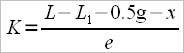
where:
L – total length of oar
L1 – inboard length of oar
0.5g – half of the gate’s width
x – distance between end of oar to a point “x”, the so called pressure point.
And spread (“e”) is considered the distance from the longitudinal ax of the boat to the pin.
Considering the above formula we realize that in the calculus of K there are included: L, x (a part of L2 , because L-L1=L2 from which we subscribe half of gate’s width and the distance from the tip of the oar to the point x).
Depending of the blade’s length and width there is a formula to calculate x.
![]()
where:
0.45 is a constant
Lb – length of blade
700 – another constant
wb – width of blade
![]()
which results that.

The formula was given for the sweep blade type Macon, but it’s also valid for Big Blade.
2 – Supporters of the English Rowing School talk about “gearing”, let’s note it with Ge, and the formula of calculus is:
3 – Researchers from the Australian Institute of Sport propose another approach, which they name “gearing ratio”, which we’ll note as Gr, and the formula for this is:
where:
L2 – outboard length of oar
and 26 is a constant.
This formula is valid for the big blade oar made by the builder Crocker with Lb=55cm(blade length) and wb=25cm (blade width).
1.1 Carl Adams’s formula although it’s the most scientific elaborated, because it can be applied to oars of different measurements, I don’t consider it to be so realistic, because the point x is too close to the oar’s shaft.
“x” could rather be a rotation point of the blade during the drive, for instance:
![]()
From this formula we notice that x is just 2.25 cm away from the oar’s shaft. Yet finding the value of x will be useful to determinate the travel distance of the boat during the drive if we know “V” (angle covered by the oar’s handle from catch to finish).
2.1 Approach of the drag factor (burden factor) after gearing:
Again, I consider this formula inconclusive because the oar’s dimensions aren’t included (blade’s width and length).
3.1 Even though it refers only to the Crocker blade, I think the Australian approach is the best yet. I propose the following formula to be used with other kinds of blades (Concept II or Empacher, which have different dimensions) :

where:
![]()
and the formula for “o” point by Carl Adam’s model,
![]()
is:
![]()
Conclusion 1:
All the three approaches talk about the drag (burden) at a given time, when the oar is in a orthogonal position (perpendicular on the longitudinal ax of the boat).
The Australian formula is valid if two sportsmen with the same Gr (gearing ratio) have the same “V”, otherwise the sportsman with the highest V angle will feel heavier the stroke and will become tired faster than the other one.
Considering all the three approaches we notice that in the calculus there appears outboard length of blade (L2) or just a part of it (Lx, Lo) and spread. Inboard length of oar and thus the total length of the oar, apparently don’t affect the drag factor (burden factor).
I worked out a formula that can offer information regarding the drag factor (burden factor) in other moments during the drive (at 35 degrees after attack or at 25 degrees before finish) and that include inboard length (L1) and the angle of the shaft at that moment but also the sportsman parameters (arm length and shoulders breadth).
Everything I talked about refers only to sweep rowing. It’s important to know that the sweep formula isn’t adequate for scull rowing.
The force of pushing against the stretcher (Fs), which is then passed to the handle through the torso and the arms, will generate a reaction force due to the lever system, named resulting force (Fr). This resulting force manifests itself in the blade pressure center and perpendicular to the blade, which decomposes according to the forces parallelogram, in two components Fr1 (propulsion force) and Fr2 (turning force).
Fr1 is the force which holds interest to us, and acts parallel to the advancing direction of the boat.
The value of this force at a certain moment of rowing will depend of cos(V1) (V1 – angle between the direction of Fr and Fr1)
![]()
Thus we will have an equality between the force applied to the handle and the internal lever, on one hand, and on the other hand the resultant force Fr and the outside lever.
![]()
where:
Fh – handle force
Fr – resulting force
in.l – internal lever
ex.l – external lever
But the force applied to the handle (Fh) depends on the force applied to the stretcher (Fs – pushing force) multiplied by sin of the angle formed by the longitudinal ax handle and the line which starts from the point situated at the middle grip on the handle (between the two fists), usually two fists distance from the tip of the handle) and the middle point of the distance between the two shoulders. (sin(θ) )
![]()
Replacing the above formula, we’ll have:
![]()
, from which
and because
Attention:
Don’t mistake internal level (in.l) with L1, and neither external level (ex.l) with L2
Eg.:
V1 = 40 degrees
θ = 65
Fs = 30 Kgf
width of one fist = 10 cm
L1 = 116 cm
L2 = 260 cm
width of the oar lock = 4 cm
in.l = L1 + 2 – 2*(width of one fist) = 116 +2 – 20 = 98cm
ex.l = L2 – 2 – 24 = 260 – 2 – 24 = 234cm
in the above formulas, the constants are:
2 – represents half of the width of the oar lock
24 – distance from the tip of the blade to the pressure center

![]()
Conclusion 2:
The propulsive force increases with the decrease of the external lever; but this doesn’t mean that we can shorten as much as we want the external lever. By shortening the external lever the propulsive force increases but the displacement of the boat shortens during the drive, and this is because there are certain limits.
We must find the optimum among the rower’s individual force, specific amplitude (A) (determined by individual physical parameters), and the ability to sustain this kind of force to a pre-established rate during all the 2000m distance.
The author of “Art of sculling”, Joe Paduda was referring to the same thing when he was stating “We must not apply a force bigger than the boat can absorb.”
When realizing an individual rigging we must keep in mind the ergometer result for 2000m (how strong is the athlete) but also the skill coefficient (the ability to translate bio-metrical qualities to water rowing performance).
When we’re talking about creating a crew and the necessity to calculate the individual drag factor (burden factor), we must also consider the individual angle made by each athlete between catch and finish.
According to the ergometer results we set first the gearing ratio for the boat (Grb) and then we calculate the individual gearing ratio:
where:
Grind = individual Gearing ratio
Grb = boat Gearing ratio
MV = average of the sum of the angles developed by each athlete
Vind = angle developed by each athlete
To set the Grb value we can guide ourselves from the rigging statistics of the World Championships of 2006. (Eton, England)
Eg.:
Athlete No.1: angle developed = 78 degrees (VNo.1 = 78)
Athlete No.2: angle developed = 80 degrees (VNo.2 = 80)
Grb = 2.75
Depending on the individual parameters of the two athletes (specific amplitude “A”, shoulders breadth “Br.s”, trunk height “H.tr”, ), we find out that athlete No.1 has “e” = 85 cm and athlete No.2 has “e” = 85,25 cm.
From the formula

results that athlete No.1 will have
![]()
and athlete No.2 will have
![]()
And because L2 = Lo + 26 results:
L2.no1 = 234.6 + 26 = 260.6
L2.no2 = 233.499 + 26 = 259.499
Thus we have realized an equilibration of the forces and we can hope that both rowers will provide maximum efficiency and their performance will be the best.
For more detailed explanation feel free to contact me.
Leave a Reply
Want to join the discussion?Feel free to contribute!